Dat 402 – Digital Culture

Dead media or zombie media?

Siegfried Zielinski’s concept of ‘deep time’ is adopted from geological research and a focus on a horizon of durations of not only thousands, or millions, but billions of years of history. For Zielinski, this idea points towards the need to look at media too in terms of their long-term relations that radically steps out of the short-term use value that is promoted by capitalist media industries. As a political and ecological twist to this, one project that takes its impulse directly from media-archaeological and dead-media debates is the Dead Media lab by Garnet Hertz – the already-mentioned California-based artist and writer. Hertz’s creative practice is informed by deep involvement in various ‘tinkering’ methodologies, from circuit bending to DIY robotics, and he has been able to connect that with media-archaeological interests – something we have, in collaboration, also called ‘zombie media’ of the living deads of media culture (Hertz and Parikka 2012).

Hertz’s project picks up Bruce Sterling’s call for a sustained interest in knowledge of media that are dead, and discarded outside normal use in everyday life – but still can have much artistic and other value. Hertz twists this further into an ecological project, or even ecosophic in the sense that Félix Guattari (2000) talks of ecosophy as reinvention of the various transversal relations between the social, the psyche, the economic and the environment. Dead Media Lab becomes hence much more than a lab for repurposing information technology – Hertz quotes the statistics on the hundreds of millions of still-operational devices that are discarded in the US alone. It is also a social laboratory for those practices that engage both in thinking about future green information technologies and in promoting community engagement in DIY methods that are inventive everyday reuses and appropriations of the art methods of the early twentieth-century avant-garde – repurposing existing media and ‘readymades’ becomes less about Duchamp and more about circuit bending and hacking workshops at community centres. It closely relates to the ‘rematerializing’ tendencies in electronic waste that force us to think about the natural history of electronics, well analysed by Jennifer Gabrys (2011).

The link to media archaeology becomes most clearly voiced in this part of his Dead Media Lab call – innovation through media history:

The history of obsolete information technology is fruitful ground for unearthing innovative projects that floundered due to a mismatch between technology and socioeconomic contexts. Because social and economic variables continually shift through time, forgotten histories and archaeologies of media provide a wealth of useful ideas for contemporary development. In other words, the history of technological obsolescence is cheap R&D that offers fascinating seeds of development for those willing to dig through it. This lab encourages the study of obsolescence and reuse in media history as a foundation for understanding the dynamics of media change. (www.conceptlab.com/deadmedia/)

As cheap R&D, media-archaeological ideas about memory, time, duration and obsolescence are part of a wider artist–activist engagement. Less a textual method, circuit bending and hardware hacking are related to thinking about media history in fresh ways that also engage with the important question of how we are able to reuse devices that too easily and too quickly end up in waste sites.

Hence, work such as Hertz’s ties in to both the lineage of media-archaeological artists such as DeMarinis, who has also been interested in the wider environmental ideas concerning media (nature as media) and equally to such initiatives as, for instance, the Mediashed in the UK. Mediashed key activity revolves around the call for ‘free media’ that are outside the proprietary platforms, and hence open both legally and technically. Mediashed’s work has focused on both software and reusing waste and junk materials (such as electronic devices and parts) for community and artistic purposes. In addition, they have shown an interest in ‘obsolescent’ forms of communication in their EcoMedia theme days and projects that expand the idea of communication to various techniques, from shouting, spitting and smelling to pigeon communication, all found in natural bodies. (For a connection to media archaeology and imaginary media, see Parikka 2011a.)

In such projects, we are moving farther away from what has usually been the safe ground of media archaeology. Even if ‘redundancy’, ‘obsolescence’, ‘time’ and ‘dead media’ connected the approaches of both free media activists and media archaeologists, the latter have, as Kahn too flagged, been reluctant to be that political. Yet to me, this link that Hertz is able to make is of crucial value in expanding media-archaeological theory and art methods. Hence, in addition to Mediashed, another clear link would also be the UK-based Redundant Technology Initiative (http://rti.lowtech.org/intro/) that grounds all of its activity in ‘technology that they could acquire for nothing’. As such, it has meant concrete spaces for Free Media tinkering (Access Space is characterized on their website as ‘an open-access digital reuse centre’ for learning and teaching), as well as projects that recircuit back to recent media history, even in the form of Mac Hypercards, ASCII-text, 28.8K faxes repurposed as part of an imaginary TV-feedback system, and manifestos promoting ‘low tech’ (http://rti.lowtech.org/).

As we argue with Hertz (Hertz and Parikka 2012), techniques of media-archaeological art like circuit bending are crucial for a wider environmental consciousness. The aesthetic tactics and various ‘minor’ methods such as circuit bending, hardware tinkering and so forth are important links to a wider activist stance towards technical media. The increasingly closed nature of consumer technology (see Guins 2009) is the other side of the coin in this call to reuse old technology. This closedness is what really defines proprietary platforms. A large amount of current consumer technology is not meant to be opened, tinkered with and reused, and this is guaranteed through various measures, ranging from Digital Rights Management that legally restricts users’ possible actions to the various design strategies that make it very difficult to engage in, for instance, circuit bending. Such techniques can indeed be seen as ‘minor’ but they are important for illuminating how technological solutions relate to power relations. Even design solutions – using glue instead of screws – are part of this wider regime of controlling patterns of (re)use (cf. Kittler 1997).

Furthermore, this relates to the wider politics of ‘planned obsolescence’ (Hertz and Parikka 2012), which can be seen as the background for much of consumer society, including technology. In such perspectives, the wider history of reuse in avant-garde art

EBSCO Publishing : eBook Collection (EBSCOhost) – printed on 3/2/2017 9:11 AM via UNIVERSITY OF PLYMOUTH AN: 572570 ; Parikka, Jussi.; What Is Media Archaeology?
Account: s4715696

73

Copyright © 2012. Polity. All rights reserved. May not be reproduced in any form without permission from the publisher, except fair uses permitted under U.S. or applicable copyright law.

from Duchamp to DJing and VJing not only is about innovations through remixing and mash-ups, but is set against the demand for originality and newness that drives production of technology. As a form of governing production and demanding constant replaceability, ‘planned obsolescence’ has, since the 1930s, been seen as a form of enforced obsolescence and as supporting new product design. Yet, during the last decades it has become even more evident that such a drive for creation is unsupportable in

terms of the ecological load it creates and distributes very unevenly as part of the global economy.


Siegfried Zielinkski – concept of time

Siegfried is a German media theorist, he was a part of the media theory: archaeology and variantology of the media at Berlin University of the arts. He wrote and directed the documentary film “Responses to HOLOCAUST in Western Germany” which is currently collected at the pale centre in New York.
In 1989 he took up his first full professorship at the university of Salzburg.

Dead media is about the explorative use of dying media recycled as a literal artistical medium. It is often associated with theorists such as; Siegfried Zielinksi whom is renowned for his theory of deep time of media which, unveils the hidden layers of media development from decades with the likes of the Greek philosopher Empedocles. Furthermore, artists like Garnet Hertz a Canadian known for his electronic artworks including the likes of circuit bending and research into the area of critical making. Overall Dead media exposes and encompasses the methodology of “Bringing in the new with the old”.

DAT 404 – Web technologies

Top 10 websites

I have made a selection of top ten websites that I can use for inspiration.

  1. Bert BV – https://bert.house/en/

Screen Shot 2017-02-27 at 13.58.38.png

2. Basic agency  – http://www.basicagency.com/yir/

Screen Shot 2017-02-27 at 14.01.04.png

3. Mike Dekker – http://mikedekker.com

Screen Shot 2017-02-27 at 14.05.39.png

4. Sennheiser –  http://www.sennheiser-reshapingexcellence.com/en#

Screen Shot 2017-02-27 at 14.12.37.png

5. Weather – https://weather.withspotify.com

Screen Shot 2017-02-27 at 14.15.29.png

6. Rainforest foods –  https://www.rainforestfoods.com/experience/#!/slide-intro

Screen Shot 2017-02-27 at 14.19.39.png

7. Kaliber – https://kaliber.net

Screen Shot 2017-02-27 at 14.22.26.png

8. Shake interactive – http://shakeinteractive.no/en/

Screen Shot 2017-02-27 at 14.24.04.png

9. Lucyhardcastle – https://lucyhardcastle-thefifthsense.i-d.co/en_gb/room/molten/

Screen Shot 2017-02-27 at 14.27.02.png

10.Indofolio – http://www.indofolio.com

Screen Shot 2017-02-27 at 14.33.10.png

DAT 405 creative coding

The brief I was given for this brief was to produce a connect 4 game with Processing an open-source language based on Java.

View the code on Github

Processing

For the past fourteen years, Processing has promoted software literacy, particularly within the visual arts, and visual literacy within technology. Initially created to serve as a software sketchbook and to teach programming fundamentals within a visual context, Processing has also evolved into a development tool for professionals. The Processing software is free and open source, and runs on the Mac, Windows, and GNU/Linux platforms.

Processing continues to be an alternative to proprietary software tools with restrictive and expensive licenses, making it accessible to schools and individual students. Its open source status encourages the community participation and collaboration that is vital to Processing’s growth. Contributors share programs, contribute code, and build libraries, tools, and modes to extend the possibilities of the software. The Processing community has written more than a hundred libraries to facilitate computer vision, data visualization, music composition, networking, 3D file exporting, and programming electronics.

Processing is currently developed primarily in Boston (at Fathom Information Design), Los Angeles (at the UCLA Arts Software Studio), and New York City (at NYU’s ITP).

Education

From the beginning, Processing was designed as a first programming language. It was inspired by earlier languages like BASIC and Logo, as well as our experiences as students and teaching visual arts foundation curricula. The same elements taught in a beginning high school or university computer science class are taught through Processing, but with a different emphasis. Processing is geared toward creating visual, interactive media, so the first programs start with drawing. Students new to programming find it incredibly satisfying to make something appear on their screen within moments of using the software. This motivating curriculum has proved successful for leading design, art, and architecture students into programming and for engaging the wider student body in general computer science classes.

Processing is used in classrooms worldwide, often in art schools and visual arts programs in universities, but it’s also found frequently in high schools, computer science programs, and humanities curricula. Museums such as the Exploratorium in San Francisco use Processing to develop their exhibitions. In a National Science Foundation-sponsored survey, students in a college-level introductory computing course taught with Processing at Bryn Mawr College said they would be twice as likely to take another computer science class as the students in a class with a more traditional curriculum.

The innovations in teaching through Processing have been adapted for the Khan Academy computer science tutorials, offered online for free. The tutorials begin with drawing, using most of the Processing functions for drawing. The Processing approach has also been applied to electronics through the Arduino and Wiring projects. Arduino uses a syntax inspired by that used with Processing, and continues to use a modified version of the Processing programming environment to make it easier for students to learn how to program robots and countless other electronics projects.

Culture

The Processing software is used by thousands of visual designers, artists, and architects to create their works. Projects created with Processing have been featured at the Museum of Modern Art in New York, the Victoria and Albert Museum in London, the Centre Georges Pompidou in Paris, and many other prominent venues. Processing is used to create projected stage designs for dance and music performances; to generate images for music videos and film; to export images for posters, magazines, and books; and to create interactive installations in galleries, in museums, and on the street. Some prominent projects include the House of Cards video for Radiohead, the MIT Media Lab’s generative logo, and the Chronograph projected software mural for the Frank Gehry-designed New World Center in Miami. But the most important thing about Processing and culture is not high-profile results – it’s how the software has engaged a new generation of visual artists to consider programming as an essential part of their creative practice.

Research

Software prototyping and data visualization are two of the most important areas for Processing developers. Research labs inside technology companies like Google and Intel have used Processing for prototyping new interfaces and services. Companies including General Electric, Nokia, and Yahoo! have used Processing to visualize their internal data. For example, the New York Times Company R&D Lab used Processing to visualize the way their news stories travel through social media. The NSF and NOAA supported research exploring phytoplankton and zooplankton diversity that was realized at the University of Washington as a dynamic ecology simulation. Researchers at the Texas Advanced Computer Center at UT Austin have used Processing to display large data visualizations across a grid of screens in the service of humanities research.

Foundation

The primary charge of the Foundation is to develop and distribute the Processing software. This includes the original Processing (Java), p5.js (Javascript), and Processing.py (Python). There is more information about the Foundation at http://foundation.processing.org/.

History

Processing was started by Ben Fry and Casey Reas in the spring of 2001, while both were graduate students at the MIT Media Lab within John Maeda’s Aesthetics and Computation research group. Development continued in their free time while Casey pursued his artistic and teaching career and Ben pursued a Ph.D. and founded Fathom Information Design. Many of the ideas in Processing go back to Muriel Cooper’s Visual Language Workshop, and it grew directly out of Maeda’s Design By Numbers project, developed at the Media Lab and released in 1999. The Wiring and Arduino projects, in turn, grew out of Processing while Casey was teaching at the Interaction Design Institute Ivrea in Italy. Processing also prompted John Resig (jQuery) to build Processing.js, a JavaScript version that then inspired more related work such as the Khan Academy curriculum in computer science. Versions of Processing that use Python, Ruby, ActionScript, and Scala are also in development. Processing and its sister projects have inspired over twenty educational books.


DAT 406PP – Digital making

PYHSICAL COMPUTING-

Arduino

Arduino is an open-source microcontroller used for building interactive object; there are a wide range of Arduino available all of which have a different design comprised of a variety of microprocessors and controllers. Arduino boarded are equipped with digital and analog input/output pins that can also be connected with expansion boards called Shields. The arduino is programmed within the Arduino IDE which is based on the C++ language however there is also integration with the Processing language; a language built on Java.

Interaction design

The practice of designing interactive digital products, environments, systems and services is how interaction design is defined; furthermore the basic principles of interaction design are also used within the curation of non digital products and physical interactive projects. The common topics of interaction design include Design, human-computer interaction and software development.

Firstly interaction design was coined by Bill Moggridge and Bill Verplank in the 1980’s. Interaction design was derivative of the Computer science term “user interface design”.

Don Norman

Don Norman is a director of the newly established Design lab at the University of California, San Diego. He comes from an Electrical Engineering and Psychology background and developed a prolific career in the User experience sphere.

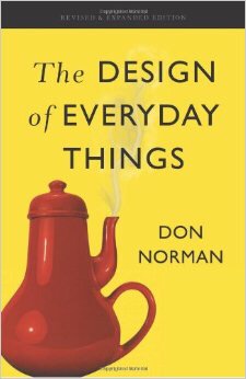
One of the most famous books is “The design of everyday things” were he talks in depth about areas such as Human-Centered design, their paradox of technology, Human cognition and emotion and Resilence Engineering plus a plethora of other related topics; however, they all relate to daily objects as the book cover suggests.

The Design of Everyday Things, Don Norman

HCI

Human-computer interaction is and active field of research and practice that emerged in the early 1980s, it embraces core subjects of cognitive science and human factors engineering. There was not much development in the field of HCI the later half of the 1980s; until the late 1970s, the only people who used a computer were information technology professionals and dedicated hobbyists. As computer technology developed at rapid rates, HCI started to incorporate, psychology, artificial intelligence , linguistics, cognitive anthropology and the philosophy of mind.

Wearable project brief
outline idea

rapid prototypes

sketch wireframes

screen-shot-2017-02-19-at-10-57-18

programming


C++ is a general-purpose programming language. It has imperative, object-oriented and generic programming features, while also providing facilities for low-level memory manipulation.

It was designed with a bias toward system programming and embedded, resource-constrained and large systems, with performance, efficiency and flexibility of use as its design highlights.C++ has also been found useful in many other contexts, with key strengths being software infrastructure and resource-constrained applications, including desktop applications, servers (e.g. e-commerce, web search or SQL servers), and performance-critical applications (e.g. telephone switches or space probes).C++ is a compiled language, with implementations of it available on many platforms and provided by various organizations, including the Free Software Foundation (FSF’s GCC), LLVM, Microsoft, Intel and IBM.


Electronics


What is Charge?

No one knows what charge really is anymore than anyone knows what gravity is. Both are models, constructions, fabrications if you like, to describe and represent something that can be measured in the real world, specifically a force. Gravity is the name for a force between masses that we can feel and measure. Early workers observed that bodies in “certain electrical condition” also exerted forces on one another that they could measure, and they invented charge to explain their observations. Amazingly, only three simple postulates or assumptions, plus some experimental observations, are necessary to explain all electrical phenomena. Everything: currents, electronics, radio waves, and light. Not many things are so simple, so it is worth stating the three postulates clearly

charge exsists  

We just invent the name to represent the source of the physical force that can be observed. The assumption is that the more charge something has, the more force will be exerted. Charge is measured in units of Coulombs, abbreviated C. The unit was named to honor Charles Augustin Coulomb (1736-1806) the French aristocrat and engineer who first measured the force between charged objects using a sensitive torsion balance he invented. Coulomb lived in a time of political unrest and new ideas, the age of Voltaire and Rousseau. Fortunately, Coulomb completed most of his work before the revolution and prudently left Paris with the storming of the Bastille.

Charge comes in two styles.

We call the two styles positive charge, , and (you guessed it) negative charge, . Charge also comes in lumps of -19C , which is about two ten-million-trillionths of a Coulomb. The  discrete nature of charge is not important for this discussion, but it does serve to indicate that a Coulomb is a LOT of charge.

Charge is conserved.

You cannot create it and you cannot annihilate it. You can, however, neutralize it. Early workers observed experimentally that if they took equal amounts of positive and negative charge and combined them on some object, then that object neither exerted nor responded to electrical forces; effectively it had zero net charge. This experiment suggests that it might be possible to take uncharged, or neutral, material and to separate somehow the latent positive and negative charges. If you have ever rubbed a balloon on wool to make it stick to the wall, you have separated charges using mechanical action.

Those are the three postulates. Now we will present some of the experimental findings that both led to them and amplify their significance.

Voltage    

First we return to the basic assumption that forces are the result of charges. Specifically, bodies with opposite charges attract, they exert a force on each other pulling them together. The magnitude of the force is proportional to the product of the charge on each mass. This is just like gravity, where we use the term “mass” to represent the quality of bodies that results in the attractive force that pulls them together .

Figure 4.1: Opposite charges exert an attractive force on each other, just like two masses attract. External force is required to hold them apart, and work is required to move them farther apart.
\begin{figure}

\fbox {\centerline{\psfig{figure=basicelec/opp-charge.I}}}\end{figure}

Electrical force, like gravity, also depends inversely on the distance squared between the two bodies; short separation means big forces. Thus it takes an opposing force to keep two charges of opposite sign apart, just like it takes force to keep an apple from falling to earth. It also takes work and the expenditure of energy to pull positive and negative charges apart, just like it takes work to raise a big mass against gravity, or to stretch a spring. This stored or potential energy can be recovered and put to work to do some useful task. A falling mass can raise a bucket of water; a retracting spring can pull a door shut or run a clock. It requires some imagination to devise ways one might hook on to charges of opposite sign to get some useful work done, but it should be possible.

The potential that separated opposite charges have for doing work if they are released to fly together is called voltage, measured in units of volts (V). (Sadly, the unit volt is not named for Voltaire, but rather for Volta, an Italian scientist.) The greater the amount of charge and the greater the physical separation, the greater the voltage or stored energy. The greater the voltage, the greater the force that is driving the charges together. Voltage is always measured between two points, in this case, the positive and negative charges. If you want to compare the voltage of several charged bodies, the relative force driving the various charges, it makes sense to keep one point constant for the measurements. Traditionally, that common point is called “ground.”

Early workers, like Coulomb, also observed that two bodies with charges of the same type, either both positive or both negative, repelled each other (Fig. 4.2). They experience a force pushing

Figure 4.2: Like charges exert a repulsive force on each other. External force is required to hold them together, and work is required to push them closer.
\begin{figure}

\fbox {\centerline{\psfig{figure=basicelec/like-charge.I}}}\end{figure}

them apart, and an opposing force is necessary to hold them together, like holding a compressed spring. Work can potentially be done by letting the charges fly apart, just like releasing the spring. Our analogy with gravity must end here: no one has observed negative mass, negative gravity, or uncharged bodies flying apart unaided. Too bad, it would be a great way to launch a space probe. The voltage between two separated like charges is negative; they have already done their work by running apart, and it will take external energy and work to force them back together.

So how do you tell if a particular bunch of charge is positive or negative? You can’t in isolation. Even with two charges, you can only tell if they are the same (they repel) or opposite (they attract). The names are relative; someone has to define which one is “positive.” Similarly, the voltage between two points  and , AB , is relative. If AB is positive you know the two points are oppositely charged, but you cannot tell if point  has positive charge and point  negative, or visa versa. However, if you make a second measurement between  and another point , you can at least tell if  and have the same charge by the relative sign of the two voltages, AB and AC to your common point . You can even determine the voltage between  and  without measuring it: BC = VAC – VAB . This is the advantage of defining a common point, like , as ground and making all voltage measurements with respect to it. If one further defines the charge at point  to be negative charge, then a positive AB means point  is positively charged, by definition. The names and the signs are all relative, and sometimes confusing if one forgets what the reference or ground point is.

Current    

Charge is mobile and can flow freely in certain materials, called conductors. Metals and a few other elements and compounds are conductors. Materials that charge cannot flow through are called insulators. Air, glass, most plastics, and rubber are insulators, for example. And then there are some materials called semiconductors, that, historically, seemed to be good conductors sometimes but much less so other times. Silicon and germanium are two such materials. Today, we know that the difference in electrical behavior of different samples of these materials is due to extremely small amounts of impurities of different kinds, which could not be measured earlier. This recognition, and the ability to precisely control the “impurities” has led to the massive semiconductor electronics industry and the near-magical devices it produces, including those on your RoboBoard. We will discuss semiconductor devices later; now let us return to conductors and charges.

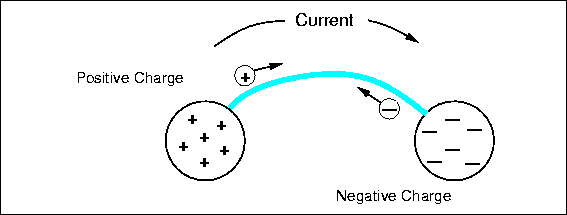
Imagine two oppositely charged bodies, say metal spheres, that are being held apart, as in Fig. 4.3.

Figure 4.3: Two spheres with opposite charges are connected by a conductor, allowing charge to flow.
\begin{figure}

\fbox {\centerline{\psfig{figure=basicelec/current.I}}}\end{figure}

There is a force between them, the potential for work, and thus a voltage. Now we connect a conductor between them, a metal wire. On the positively charged sphere, positive charges rush along the wire to the other sphere, repelled by the nearby similar charges and attracted to the distant opposite charges. The same thing occurs on the other sphere and negative charge flows out on the wire. Positive and negative charges combine to neutralize each other, and the flow continues until there are no charge differences between any points of the entire connected system. There may be a net residual charge if the amounts of original positive and negative charge were not equal, but that charge will be distributed evenly so all the forces are balanced. If they were not, more charge would flow. The charge flow is driven by voltage or potential differences. After things have quieted down, there is no voltage difference between any two points of the system and no potential for work. All the work has been done by the moving charges heating up the wire.

The flow of charge is called electrical current. Current is measured in amperes (a), amps for short (named after another French scientist who worked mostly with magnetic effects). An ampere is defined as a flow of one Coulomb of charge in one second past some point. While a Coulomb is a lot of charge to have in one place, an ampere is a common amount of current; about one ampere flows through a 100 watt incandescent light bulb, and a stove burner or a large motor would require ten or more amperes. On the other hand low power digital circuits use only a fraction of an ampere, and so we often use units of  of an ampere, a milliamp, abbreviated as ma, and even  of a milliamp, or a microamp, . The currents on the RoboBoard are generally in the milliamp range, except for the motors, which can require a full ampere under heavy load. Current has a direction, and we define a positive current from point  to  as the flow of positive charges in the same direction. Negative charges can flow as well, in fact, most current is actually the result of negative charges moving. Negative charges flowing from  to  would be a negative current, but, and here is the tricky part, negative charges flowing from  to  would represent a positive current from  to . The net effect is the same: positive charges flowing to neutralize negative charge or negative charges flowing to neutralize positive charge; in both cases the voltage is reduced and by the same amount.

Batteries    

Charges can be separated by several means to produce a voltage. A battery uses a chemical reaction to produce energy and separate opposite sign charges onto its two terminals. As the charge is drawn off by an external circuit, doing work and finally returning to the opposite terminal, more chemicals in the battery react to restore the charge difference and the voltage. The particular type of chemical reaction used determines the voltage of the battery, but for most commercial batteries the voltage is about 1.5 V per chemical section or cell. Batteries with higher voltages really contain multiple cells inside connected together in series. Now you know why there are 3 V, 6 V, 9 V, and 12 V batteries, but no 4 or 7 V batteries. The current a battery can supply depends on the speed of the chemical reaction supplying charge, which in turn often depends on the physical size of the cell and the surface area of the electrodes. The size of a battery also limits the amount of chemical reactants stored. During use, the chemical reactants are depleted and eventually the voltage drops and the current stops. Even with no current flow, the chemical reaction proceeds at a very slow rate (and there is some internal current flow), so a battery has a finite storage or shelf life, about a year or two in most cases. In some types of batteries, like the ones we use for the robot, the chemical reaction is reversible: applying an external voltage and forcing a current through the battery, which requires work, reverses the chemical reaction and restores most, but not all, the chemical reactants. This cycle can be repeated many times. Batteries are specified in terms of their terminal voltage, the maximum current they can deliver, and the total current capacity in ampere-hours.

You should handle batteries carefully, especially the ones we use in this course. Chemicals are a very efficient and compact way of storing energy. Just consider the power of gasoline or explosives, or the fact that you can play soccer for several hours powered only by a slice of cold pizza for breakfast. Never connect the terminals of a battery together with a wire or other good conductor. The battery we use for the RoboBoard is similar to the battery in cars, which uses lead and sulphuric acid as reactants. Such batteries can deliver very large currents through a short circuit, hundreds of  amperes. The large current will heat the wire and possibly burn you; the resulting rapid internal chemical reactions also produce heat and the battery can explode, spreading nasty, reactive chemicals about. Charging these batteries with too large a current can have the same effect. Double check the circuit and instructions before connecting a battery to any circuit. More information on batteries can be found in Chapter 7.

Circuit Elements

Resistors    


We need some way to control the flow of current from a voltage source, like a battery, so we do not melt wires and blow up batteries. If you think of current, charge flow, in terms of water flow, a good electrical conductor is like big water pipe. Water mains and fire hoses have their uses, but you do not want to take a drink from one. Rather, we use small pipes, valves, and other devices to limit water flow to practical levels. Resistors do the same for current; they resist the flow of charge; they are poor conductors. The value of a resistor is measured in ohms and represented by the Greek letter capital omega. There are many different ways to make a resistor. Some are just a coil of wire made of a material that is a poor conductor. The most common and inexpensive type is made from powdered carbon and a glue-like binder. Such carbon composition resistors usually have a brown cylindrical body with a wire lead on each end, and colored bands that indicate the value of the resistor. The key to reading these values is given in Chapter 2.

There are other types of resistors in your robot kit. The potentiometer is a variable resistor. When the knob of a potentiometer is turned, a slider moves along the resistance element. Potentiometers generally have three terminals, a common slider terminal, and one that exhibits increasing resistance and one that has decreasing resistance relative to the slider as the  shaft is turned in one direction. The resistance between the two stationary contacts is, of course, fixed, and is the value specified for the potentiometer. The photoresistor or photocell is composed of a light sensitive material. When the photocell is exposed to more light, the resistance decreases. This type of resistor makes an excellent light sensor.

Ohm’s Law

Ohm’s law describes the relationship between voltage, , which is trying to force charge to flow, resistance, , which is resisting that flow, and the actual resulting current . The relationship is simple and very basic: \begin{displaymath}
V = I R \quad{\rm or}\quad I = {V \over R} \end{displaymath}.   Thus large voltages and/or low resistances produce large currents. Large resistors limit current to low values. Almost every circuit is more complicated than just a battery and a resistor, so which voltage does the formula refer to? It refers to the voltage across the resistor, the voltage between the two terminal wires. Looked at another way, that voltage is actually produced by the resistor. The resistor is restricting the flow of charge, slowing it down, and this creates a traffic jam on one side, forming an excess of charge with respect to the other side. Any such charge difference or separation results in a voltage between the two points, as explained above. Ohm’s law tells us how to calculate that voltage if we know the resistor value and the current flow. This voltage drop is analogous to the drop in water pressure through a small pipe or small nozzle.

Power    

Current flowing through a poor conductor produces heat by an effect similar to mechanical friction. That heat represents energy that comes from the charge traveling across the voltage difference. Remember that separated charges have the potential to do work and provide energy. The work involved in heating a resistor is not very useful, unless we are making a hotplate; rather it is a byproduct of restricting the current flow. Power is measured in units of watts (W), named after James Watt, the Englishman who invented the steam engine, a device for producing lots of useful power. The power that is released into the resistor as heat can be calculated as , where  is the current flowing through the resistor and  is the voltage across it. Ohm’s law relates these two quantities, so we can also calculate the power as \begin{displaymath}
P = {V^2 \over R} \quad {\rm or}\quad P = I^2 R \end{displaymath}The power produced in a resistor raises its temperature and can change its value or destroy it. Most resistors are air-cooled and they are made with different power handling capacity. The most common values are 1/8, 1/4, 1, and 2 watt resistors, and the bigger the wattage rating, the bigger the resistor physically. Some high power applications use special water cooled resistors. Most of the resistors on the RoboBoard are 1/8 watt.

Combinations of Resistors   

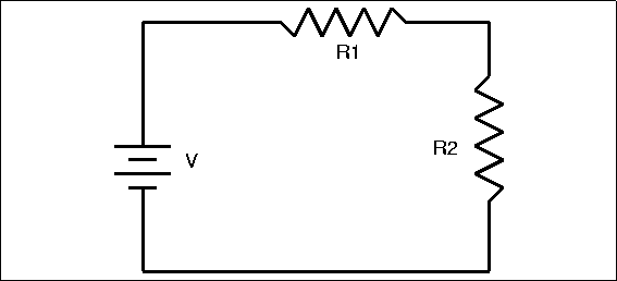
Resistors are often connected together in a circuit, so it is necessary to know how to determine the resistance of a combination of two or more resistors. There are two basic ways in which resistors can be connected: in series and in parallel. A simple series resistance circuit is shown in Figure 4.4.

Figure 4.4: Two Resistors in Series
\begin{figure}

\fbox {\centerline{\psfig{figure=basicelec/resseries.PS}}}\end{figure}

Determining the total resistance for two or more resistors in series is very simple. Total resistance equals the sum of the individual resistances. In this case, T=R1+R2 . This makes common sense; if you think again in terms of water flow, a series of obstructions in a pipe add up to slow the flow more than any one. The resistance of a series combination is always greater than any of the individual resistors.

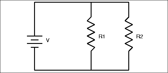
The other method of connecting resistors is shown in Figure 4.5, which shows a simple parallel resistance circuit.

Figure 4.5: Two Resistors in Parallel
\begin{figure}

\fbox {\centerline{\psfig{figure=basicelec/resparallel.PS}}}\end{figure}

Our water pipe analogy indicates that it should be easier for current to flow through this multiplicity of paths, even easier than it would be to flow through any single path. Thus, we expect a parallel combination of resistors to have less resistance than any one of the resistors. Some of the total current will flow through R1 and some will flow through R2, causing an equal voltage drop across each resistor. More current, however, will flow through the path of least resistance. The formula for total resistance in a parallel circuit is more complex than for a series circuit:

T={1{1R1}+{1R2}…+{1Rn}}

(1)

Parallel and series circuits can be combined to make more complex structures, but the resulting complex resistor circuits can be broken down and analyzed in terms of simple series or parallel circuits. Why would you want to use such combinations? There are several reasons; you might use a combination to get a value of resistance that you needed but did not have in a single resistor. Resistors have a maximum voltage rating, so a series of resistors might be used across a high voltage. Also, several low power resistors can be combined to handle higher power. What type of connection would you use?

Capacitors    


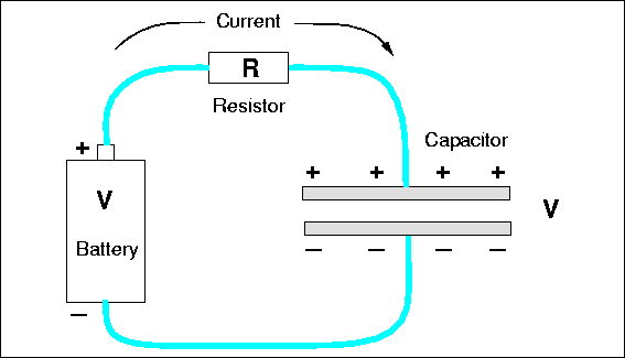
Capacitors are another element used to control the flow of charge in a circuit. The name derives from their capacity to store charge, rather like a small battery. Capacitors consist of two conducting surfaces separated by an insulator; a wire lead is connected to each surface. You can imagine a capacitor as two large metal plates separated by air, although in reality they usually consist of thin metal foils or films separated by plastic film or another solid insulator, and rolled up in a compact package. Consider connecting a capacitor across a battery, as in Fig. 4.6.

Figure 4.6: A simple capacitor connected to a battery through a resistor.
\begin{figure}

\fbox {\centerline{\psfig{figure=basicelec/capacitor.I}}}\end{figure}

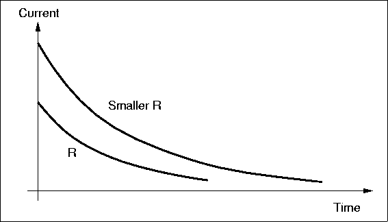
As soon as the connection is made charge flows from the battery terminals, along the wire and onto the plates, positive charge on one plate, negative charge on the other. Why? The like-sign charges on each terminal want to get away from each other. In addition to that repulsion, there is an attraction to the opposite-sign charge on the other nearby plate. Initially the current is large, because in a sense the charges can not tell immediately that the wire does not really go anywhere, that there is no complete circuit of wire. The initial current is limited by the resistance of the wires, or perhaps by a real resistor, as we have shown in Fig. 4.6. But as charge builds up on the plates, charge repulsion resists the flow of more charge and the current is reduced. Eventually, the repulsive force from charge on the plate is strong enough to balance the force from charge on the battery terminal, and all current stops. Figure 4.7 shows how the current might vary with

Figure 4.7: The time dependence of the current in the circuit of Fig. 4.6 for two values of resistance.
\begin{figure}

\fbox {\centerline{\psfig{figure=basicelec/decay.I}}}\end{figure}

time for two different values of resistors. For a large resistor, the whole process is slowed because the current is less, but in the end, the same amount of charge must exist on the capacitor plates in both cases. The magnitude of the charge on each plate is equal.

The existence of the separated charges on the plates means there must be a voltage between the plates, and this voltage be equal to the battery voltage when all current stops. After all, since the points are connected by conductors, they should have the same voltage; even if there is a resistor in the circuit, there is no voltage across the resistor if the current is zero, according to Ohm’s law. The amount of charge that collects on the plates to produce the voltage is a measure of the value of the capacitor, its capacitance, measured in farads (f). The relationship is , where Q is the charge in Coulombs. Large capacitors have plates with a large area to hold lots of charge, separated by a small distance, which implies a small voltage. A one farad capacitor is extremely large, and generally we deal with microfarads (), one millionth of a farad, or picofarads (pf), one trillionth -12) of a farad.

Consider the   circuit of Fig. 4.6 again. Suppose we cut the wires after all current has stopped flowing. The charge on the plates is now trapped, so there is still a voltage between the terminal wires. The charged capacitor looks somewhat like a battery now. If we connected a resistor across it, current would flow as the positive and negative charges raced to neutralize each other. Unlike a battery, there is no mechanism to replace the charge on the plates removed by the current, so the voltage drops, the current drops, and finally there is no net charge left and no voltage differences anywhere in the circuit. The behavior in time of the current, the charge on the plates, and the voltage looks just like the graph in Fig. 4.7. This curve is an exponential function: . The voltage, current, and charge fall to about 37% of their starting values in a time of  seconds, which is called the characteristic time or the time constant of the circuit. The  time constant is a measure of how fast the circuit can respond to changes in conditions, such as attaching the battery across the uncharged capacitor or attaching a resistor across the charged capacitor. The voltage across a capacitor cannot change immediately; it takes time for the charge to flow, especially if a large resistor is opposing that flow. Thus, capacitors are used in a circuit to damp out rapid changes of voltage.

Combinations of Capacitors   

Like resistors, capacitors can be joined together in two basic ways: parallel and series. It should be obvious from the physical construction of capacitors that connecting two together in parallel results in a bigger capacitance value. A parallel connection results in bigger capacitor plate area, which means they can hold more charge for the same voltage. Thus, the formula for total capacitance in a parallel circuit is:

T=C1+C2…+Cn , 

(2)

the same form of equation for resistors in series, which can be confusing unless you think about the physics of what is happening.

The capacitance of a series connection is lower than any capacitor because for a given voltage across the entire group, there will be less charge on each plate. The total capacitance in a series circuit is

T={1{1C1}+{1C2}…+{1Cn}}.

(3)

Again, this is easy to confuse with the formula for parallel resistors, but there is a nice symmetry here.

Inductors    

Inductors are the third and final type of basic circuit component. An inductor is a coil of wire with many windings, often wound around a core made of a magnetic material, like iron. The properties of inductors derive from a different type of force than the one we invented charge to explain: magnetic force rather than electric force. When current flows through a coil (or any wire) it produces a magnetic field in the space outside the wire, and the coil acts just like any natural, permanent magnet, attracting iron and other magnets. If you move a wire through a magnetic field, a current will be generated in the wire and will flow through the associated circuit. It takes energy to move the wire through the field, and that mechanical energy is transformed to electrical energy. This is how an electrical generator works. If the current through a coil is stopped, the magnetic field must also disappear, but it cannot do so immediately. The field represents stored energy and that energy must go somewhere. The field contracts toward the coil, and the effect of the field moving through the wire of the coil is the same as moving a wire through a stationary field: a current is generated in the coil. This induced current acts to keep the current flowing in the coil; the induced current opposes any change, an increase or a decrease, in the current through the inductor. Inductors are used in circuits to smooth the flow of current and prevent any rapid changes.

The current in an inductor is analogous to the voltage across a capacitor. It takes time to change the voltage across a capacitor, and if you try, a large current flows initially. Similarly, it takes time to change the current through an inductor, and if you insist, say by opening a switch, a large voltage will be produced across the inductor as it tries to force current to flow. Such induced voltages can be very large and can damage other circuit components, so it is common to connect some element, like a resistor or even a capacitor across the inductor to provide a current path and absorb the induced voltage. (Often, a diode, which we will discuss later, is used.)

Inductors are measured in henrys (h), another very big unit, so you are more likely to see millihenries, and microhenries. There are almost no inductors on the RoboBoard, but you will be using some indirectly: the motors act like inductors in many ways. In a sense an electric motor is the opposite of an electrical generator. If current flows through a wire that is in a magnetic field (produced either by a permanent magnet or current flowing through a coil), a mechanical force will be generated on the wire. That force can do work. In a motor, the wire that moves through the field and experiences the force is also in the form of a coil of wire, connected mechanically to the shaft of the motor. This coil looks like and acts like an inductor; if you turn off the current (to stop the motor), the coil will still be moving through the magnetic field, and the motor now looks like a generator and can produce a large voltage. The resulting inductive voltage spike can damage components, such as the circuit that controls the motor current. In the past this effect destroyed a lot of motor controller chips and other RoboBoard components. The present board design contains special diodes that will withstand and safely dissipate the induced voltages — we hope.

Combinations of Inductors

You already know how inductors act in combination because they act just like resistors. Inductance adds in series. This makes physical sense because two coils of wire connected in series just looks like a longer coil. Parallel connection reduces inductance because the current is split between the several coils and the fields in each are thus weaker.

Semiconductor Devices

The Truth About Charge   

Our statements above about charge are not wrong, but they are simple and incomplete. In order to understand how semiconductor devices work one needs a more complete description of the nature of charge in the real world. Charge does not exist independently; it is carried by subatomic particles. For this discussion we will be concerned primarily with electrons, which carry a negative charge of -19 C , the minimum amount of charge that can exist in isolation. At least, no one has found any smaller amount than this fundamental quantum of charge.

Electrons are one component of atoms and molecules. Atoms are the building blocks out of which all matter is constructed. Atoms bond with each other to form substances. Substances composed of just one type of atom are called elements. For example, copper, gold and silver are all elements; that is, each of them consists of only one type of atom. More complex substances are made up of more than one atom and are known as compounds. Water, which has both hydrogen and oxygen atoms, is such a compound. The smallest unit of a compound is a molecule. A water molecule, for example, contains two hydrogen atoms and one oxygen atom.

Atoms themselves are made up of even smaller components: protonsneutrons and electrons. Protons and neutrons form the nucleus of an atom, while the electrons orbit the nucleus. Protons carry positive charge and electrons carry negative charge; the magnitude of the charge for both particles is the same, one quantum charge, -19 C . Neutrons are not charged. Normally, atoms have the same number of protons and electrons and have no net electrical charge.

Figure 4.8: Structure of an Atom
\begin{figure}

\fbox {\centerline{\psfig{figure=basicelec/atomstruct.PS}}}\end{figure}

Electrons that are far from the nucleus are relatively free to move around under the influence of external fields because the force of attraction from the positive charge in the nucleus is weak at large distances. In fact, it takes little force in many cases to completely remove an outer electron from an atom, leaving an ion with a net positive charge. Once free, electrons can move at speeds approaching the speed of light (roughly 670 million miles per hour) through metals, gases and vacuum. They can also become attached to another atom, forming an ion with net negative charge.

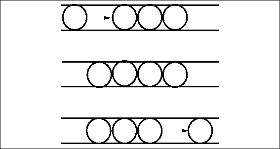
Electric current in metal conductors consists of a flow of free electrons. Because electrons have negative charge, the flow of electrons is in a direction opposite to the positive current. Free electrons traveling through a conductor drift until they hit other electrons attached to atoms. These electrons are then dislodged from their orbits and replaced by the formerly free electrons. The newly freed electrons then start the process anew. At the microscopic level, electron flow through a conductor is not a steady stream, like water flowing from a faucet, but rather a series of short bursts.

Figure 4.9: A Simple Model of Electron Flow
\begin{figure}

\fbox {\centerline{\psfig{figure=basicelec/eflow.PS}}}\end{figure}

Silicon    

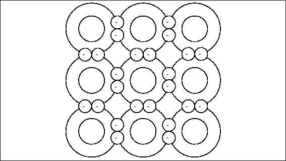
Semiconductor devices are made primarily of silicon (silicon’s element symbol is “Si”). Pure silicon forms rigid crystals because of its four valence (outermost) electron structure — one Si  atom bonds to four other Si atoms forming a very regularly shaped diamond pattern. Figure 4.10 shows part of a silicon crystal structure.

Figure 4.10: A Silicon Crystal Structure
\begin{figure}

\fbox {\centerline{\psfig{figure=basicelec/silicon.PS}}}\end{figure}

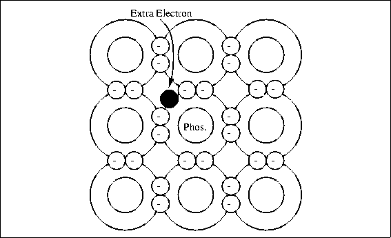
Pure silicon is not a conductor because there are no free electrons; all the electrons are tightly bound to neighboring atoms. To make silicon conducting, producers combine or “dope” pure silicon with very small amounts of other elements like boron or phosphorus. Phosphorus has five outer valence electrons. When three silicon atoms and one phosphorus atom bind together in the basic silicon crystal cell of four atoms, there is an extra electron and a net negative charge. Figure4.11 shows the crystal structure of phosphorus doped silicon.

Figure 4.11: Silicon Doped with Phosphorus
\begin{figure}

\fbox {\centerline{\psfig{figure=basicelec/phosphorus.PS}}}\end{figure}

This type of material is called n-type silicon. The extra electron in the crystal cell is not strongly attached and can be released by normal thermal energy to carry current; the conductivity depends on the amount of phosphorus added to the silicon.

Boron has only three valance electrons. When three silicon atoms and one boron atom bind with each other there is a “hole” where another electron would be if the boron atom were silicon; see Fig. 4.12. This gives the crystal cell a positive net charge (referred to as p-type silicon), and the ability to pick up an electron easily from a neighboring cell.

Figure 4.12: Silicon Doped with Boron
\begin{figure}

\fbox {\centerline{\psfig{figure=basicelec/boron.PS}}}\end{figure}

The resulting migration of electron vacancies or holes acts like a flow of positive charge through the crystal and can support a current. It is sometimes convenient to refer to this current as a flow of positive holes, but in fact the current is really the result of electrons moving in the opposite direction from vacancy to vacancy.

Diodes    


Both p-type and n-type silicon will conduct electricity just like any conductor; however, if a piece of silicon is doped p-type in one section and n-type in an adjacent section, current will flow in only one direction across the junction between the two regions. This device is called a diode and is one of the most basic semiconductor devices.

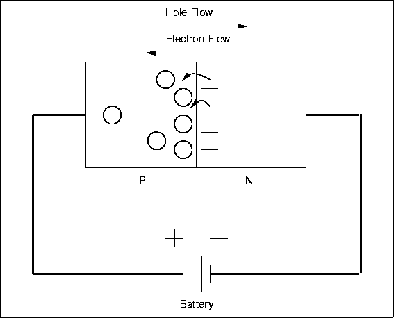
A diode is called forward biased if it has a positive voltage across it from from the p- to n-type material. In this condition, the diode acts rather like a good conductor, and current can flow, as in Fig. 4.13.

Figure 4.13: A Forward Biased Diode
\begin{figure}

\fbox {\centerline{\psfig{figure=basicelec/fbdiode.PS}}}\end{figure}

There will be a small voltage across the diode, about 0.6 volts for Si, and this voltage will be largely independent of the current, very different from a resistor.

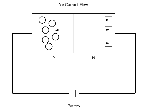
If the polarity of the applied voltage is reversed, then the diode will be reverse biased and will appear nonconducting (Fig. 4.14). Almost no current will flow and there will be a large voltage across the device.

Figure 4.14: A Reverse Biased Diode
\begin{figure}

\fbox {\centerline{\psfig{figure=basicelec/rbdiode.PS}}}\end{figure}

The non-symmetric behavior is due to the detailed properties of the pn-junction. The diode acts like a one-way valve for current and this is a very useful characteristic. One application is to convert alternating current (AC), which changes polarity periodically, into direct current (DC), which always has the same polarity. Normal household power is AC while batteries provide DC, and converting from AC to DC is called rectification. Diodes are used so commonly for this purpose that they are sometimes called rectifiers, although there are other types of rectifying devices. Figure 4.15 shows the input and output current for a simple half-wave

Figure 4.15: A Half-Wave Rectifier
\begin{figure}

\fbox {\centerline{\psfig{figure=basicelec/halfrect.PS}}}\end{figure}

rectifier. The circuits gets its name from the fact that the output is just the positive half of the input waveform. A full-wave rectifier circuit (shown in Figure 4.16) uses four diodes arranged so that both polarities of the input waveform can be used at the output.

Figure 4.16: A Full-Wave Rectifier
\begin{figure}

\fbox {\centerline{\psfig{figure=basicelec/fullrect.PS}}}\end{figure}

The full-wave circuit is more efficient than the half-wave one.

Throughout the modul we have started to learn Arduinos C++ based IDE.

DAT 403

This module is focused about learning and honing our skills within the adobe suite, focusing on Photoshop, Illustrator and After effects.

The first session we mainly learned about cutting with the selection tool which was fairly basic however in the second practical session we learned about how to manipulate something once you have cut it out.

screen-shot-2016-10-25-at-13-54-51

The image above is the one I used to manipulate.

BRIEF:

There are 3 projects to submit for marking. 2 graphics design project, the 1st in Illustrator, the 2nd in Photoshop. The 3rd project will be an animation show reel. Each project will be aimed towards your personal portfolios, so you should strive to push your individual design and creative media production skills.

LOGO

initial ideas

screen-shot-2016-11-02-at-10-21-08

These were my initial ideas which produced on my iPad, they all incorporate elements of a circular type; which is very relevant to the brief. I think the one I will develop further will be the last one on the bottom row.

screen-shot-2016-11-02-at-10-42-23

This was my development of the first idea, I really like the shape and dynamic of the logo; however I think I need to do some typographic experiments to see which lettering fits best with the shape at the moment.

screenshot-2016-11-07-16-19-31

This is my typography comparison to see which experiments with a range o different type sets to see which works best with he general shape and dynamic of my logo; overall I like think the bottom left logo works the best (using Balboaplus), as the general shapes is fairly overpowering and strong therefore needs a bold type face to accompany it.

screenshot-2016-11-07-18-45-45

At this stage in the brief, I tried to experiment with different creative aesthetics and decided the logo below looked best and had both a creative flare and encapsulated what the IVT is.

screenshot-2016-11-07-17-01-52

This is the final logo shape.

screenshot-2016-11-07-17-31-09

Now I had a final logo shape to work with I had to come up with a colour palette which was fairly easy considering I already had a defined idea of what I wanted the final product to look like. I firstly tried grey which didn’t stand out enough, and thought something with a bit more of a punch would work better; thus I tried pink which was overkill and was to brash. Finally I tried a light green which worked perfectly with the black type. I also tried to play with the stroke and fill of the type and decided to stick with the below image.

Final int logo.png

This is the final logo. I used a range of creative process to produce my final logo; such as sketching, typography tests and colour experiments. The logo was produced Adobe illustrator and used the pen and circle tool to create the basic shape; I then developed this further by changing the line type which with the colour and type choices makes for a clean and precise logo with a creative flare.


Poster


screen-shot-2016-11-19-at-17-47-36

Firstly I used Adobe Comp to produce a basic outline for my poster, I wanted the centre focus to be on a main illustration accompanied by a bold sans typography.


img_0003

I then used my iPad Pro and Adobe Photoshop sketch to produce the main illustration which I based on a nebula but in a watercolour style, with watermarks leaking out; I felt this would pull the poster together as it would leak over the surrounding type.

img_0002

I then brought the logo back into Adobe comp to see what it looked like, and felt it would compliment my chosen fonts.

poster.jpg

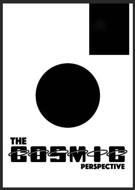
This is my final poster for The Cosmic Perspective event, overall I think it is a success and all the elements and the way they were applied makes the poster not only noticeable with a plethora of colours but also effective in its approach in communicate the basic information about the event.

University -DAT 401

Collaboration and crowdsourcing project (Lecture 1)

Crowdsourcing requires small contributions from many people in return they get the product when its realised or something else equivocal to the amount they contributed.

Relies on:

  • Strong and initial idea
  • clear outcome expected from the project
  • outsourcing

The difference between factory manufacturing and crowdsourcing

Factory 

  • Small contribution
  • central control
  • high obligation
  • high pay, labour laws
  • protection for workers

Crowdsourcing

  • Small contributions
  • central control
  • no protection
  • low commitment
  • low pay

Main Keywords/Phrases

  • New labour model?
  • zero hours contract
  • Digital rights managment
  • Creative commons

Crowdsourcing for the common good

Collaborative efforts are low risk for each participant, which enables financial ability something that a large company is unwilling to risk.

Main things to consider

  • Clear, complete instructions
  • Assemble the resulting submissions
  • Quality control

Assignment – Produce a crowdsourced 2d piece.


What is digital art? (Practical 1)

I firstly had to look a plethora of examples of different types of digital art, which are below:

Net Art: Ben Benjamin: Superbad.com

Interactive Installation: Scott Snibbe: Boundary functions

Augmented Gaming: Blast Theory: Can you see me now http://www.blasttheory.co.uk/projects/can-you-see-me-now/

Evolutionary Art: William Latham’s mutator https://www.youtube.com/watch?v=AN6ngsckRZs

Critical media art: Jonah Bruckner-Cohen: Police state http://www.coin- operated.com/

Data Visualisation: Aaron Koblin: flight patterns: http://www.aaronkoblin.com/work/flightpatterns/

Critical media art: Caleb Larsen A tool to Deceive and Slaughter http://caleblarsen.com/a-tool-to-deceive-and-slaughter/

VR: Jennifer Kanary: Labyrinth Psychotica wearable: https://www.youtube.com/watch?v=7_tl63oxiqg

Audiovisual installation: Ryoji Ikeda https://www.youtube.com/watch?v=omDK2Cm2mwo

Critical media art: Paolo Cirio and Alessandro Ludovico: Face to Facebook http://www.face-to-facebook.net/

Glitch Art: Rosa Menkman http://rosa-menkman.blogspot.co.uk/

Interactive Installation: Random International: The rain room http://random-international.com/work/rainroom/

Net Art: Jodi.org http://ubu.com/film/jodi_osx.html

Glitch Art: Jon Satrom: http://jonsatrom.com/ http://jonsatrom.com/about/index.html

The next step was to select one artist and write 300 words which:

1) described the project in your own words

2) write a short biography of the artist

3) explain what you find interesting / challenging about the work. Has it changed your perception of digital art and if so, how?

Artist Research 

VR: Jennifer Kanary: Labyrinth Psychotica wearable: Click here for Video

I think the project is?

I think this project is based around Virtual Reality but unlike majority of examples where VR is used to produce a game; this has used VR to produce a experience which is enlightening to a real world problem psychosis. Jennifer Kanary get the experience as accurate as possible by stimulating all the sense with exceptions to touch and smell.

Jennifer Kanary

Jennifer Kanary is an independent  artist whom studied fashion design however after completing her masters at the university of Amsterdam, her creative area changed. Jennifer Kanary has participated in a wider array of projects such as: Battle of the Universities, Kloone4000 and Discovery07. Since 2006 she has embarked on the challenge of a Artistic research PhD with The Planetary Collegium, Plymouth University, M-Node NABA. Kanary has a current aim to understand philosophical relation between art and scientific research in psychosis simulators, which are used to understand the symptoms of schizophrenia.

What I found interesting and has it changed your opinion on digital art ?

What I found most compelling was the effect it had on the people after they experienced the VR. “You retreat into a cocoon, that is very realistic”, “It dragged me in deeper and deeper”these quotes suggest that they found the experience had so much stimuli that it resulted in a extremely realistic experience and allowed the viewer to be immersed in what a person who actual experiences psychosis goes through. I typically thought that all art including digital art was all about self expression and had no real impact on others, however this piece has proven otherwise; it shows how can open someones eyes to someones else problems which in-turn allows solution to be found.

Oblique Card


Divergent and lateral thinking (Practical 2)

Plastic cup

  1. Plastic
  2. Recyclable
  3.  Malleable
  4. Water proof
  5. Light weight
  6. Long lasting

Uses

  1. Holds liquid
  2. Pen holder
  3. Pipe
  4. Watering cup
  5. Voice changer
  6. Pet Feeder

Random Noun assocation

  1. Lace = Hat
  2. Sand = sand castle
  3. Sock = sock manakin
  4. Sneeze = Sneeze catcher
  5. Wrist = bracelet
  6.  Dogs = Poop scoop

Leather Wallet

  1. storage
  2. easy access
  3. Leather
  4. water proof
  5. durable
  6. portable

Uses

  1. slippers
  2. (Melanie) Food wallet
  3. phone case
  4. plant pot
  5. bottle holder
  6. oven glove

Random Noun association

  1. pet = collar
  2. fall = crash mat
  3. egg = egg cup
  4. death = suffication
  5. waste = waste bag
  6. lettuce = colander

Hose

  1. Waterproof
  2. Malleable
  3. Long
  4. Thick
  5. Cheap
  6. Hollow

Uses

  1. Skipping rope
  2. Snorkel
  3. Trumpet
  4. Telepipe
  5. Sprinkler
  6. garrote

Practical (10.12.16)

Data Hacking

Data hacking is based on the idea of using a file in the unconventional manner, for example turning a .jpg image into a .txt file changing some of the code and the converting it back into . jpg;  this will produce a some sort of creative effect. This base concept can also be expanded, such as turning a .jpg into a .wav file to produce a strange audio effect.

new-york
Original image

Original image

new-york-copy
Data bending with modifications to the .txt extension
new-york-copy-2-jp
This is the image with further changes to the .txt file
new-york-6
Finally this is my favourite as this was converted into a raw from a .jpg then into a .txt were i changed some of the code then back into adobe photoshop where I exported as a unleaved RGB .raw file.

The excersise above enlightened me to the idea of changing crucial elements of documents to produce a effect. This also allows me to fully understand what documents such as images are built up off further developing my computional skills.


Practical (10-18-2016)

Today we looked at mash-ups and shreds; this allowed me to develop practical skills in premiere pro. The mash-up I created is below.

Practical(10-19-2016)

Reflection on our main interventions project:

How did you make the work?

To make the work we used canvas to produce the plasters and then double sticky tape apply them to the public surface.
How do you get inspiration?

For inspiration we looked at examples of social interventions and found a example of a artist who fills cracks in building with lego; this highlights the crack and therefore makes the crack more likely to be filled.This inspired us as a group a lot and thus we developed our own interpretation of this idea.
Did you work on the first idea you had or create lots of ideas and pick one? Did the work evolve?

As a group we’ve had a few meetings to develop ideas, the first idea which was originally going to go for was real life google map pins; after further research we realised that this idea has been done several times thus not original.
What would you do differently next time?

If I were to do this again,I would make sure our group was more organised and had better time management.
Did you make things difficult for yourself?

As our group was a bit broken and didn’t co-operate with everyone fully it made things harder. Time management was by far the biggest difficulty for our group.


Blog at WordPress.com.

Up ↑